TECHNICAL DRAWINGS DESIGN
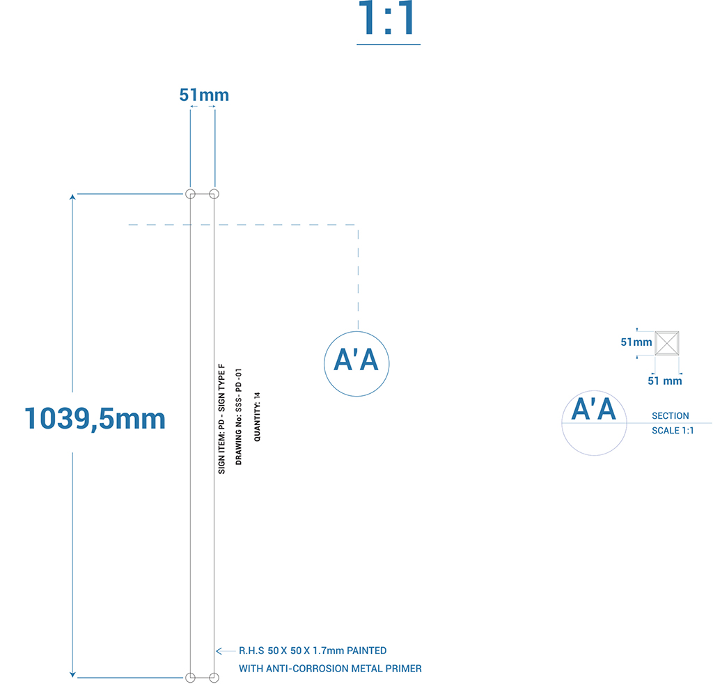
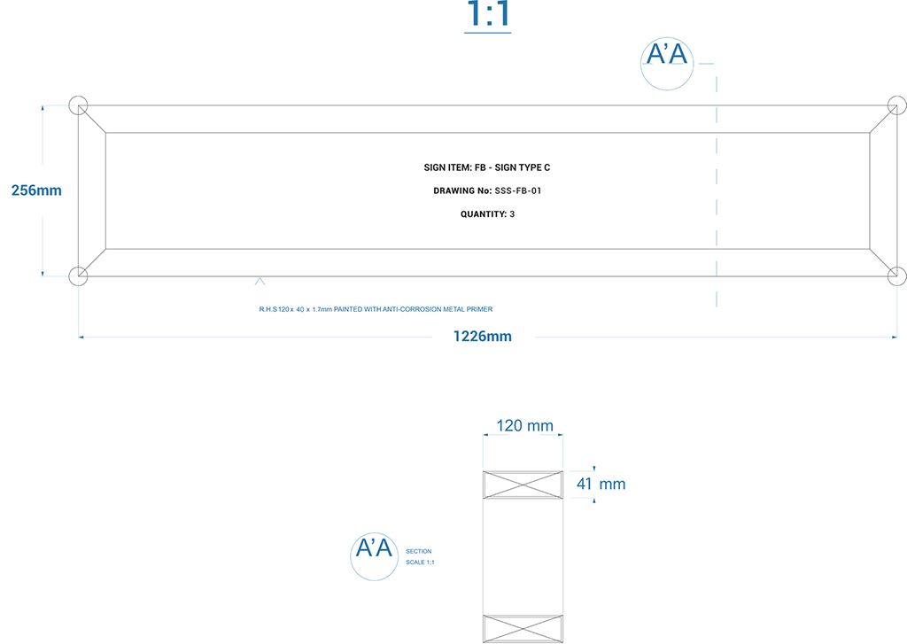
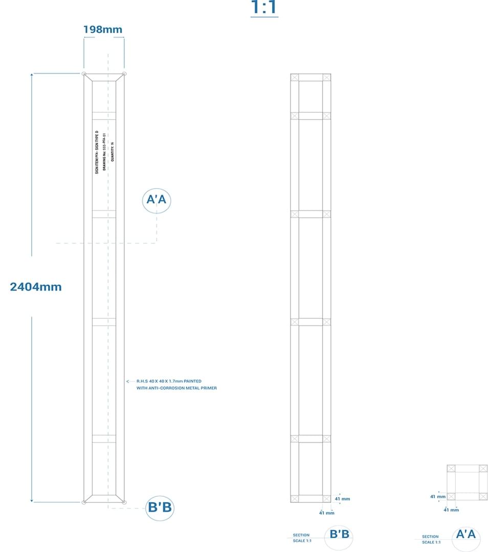
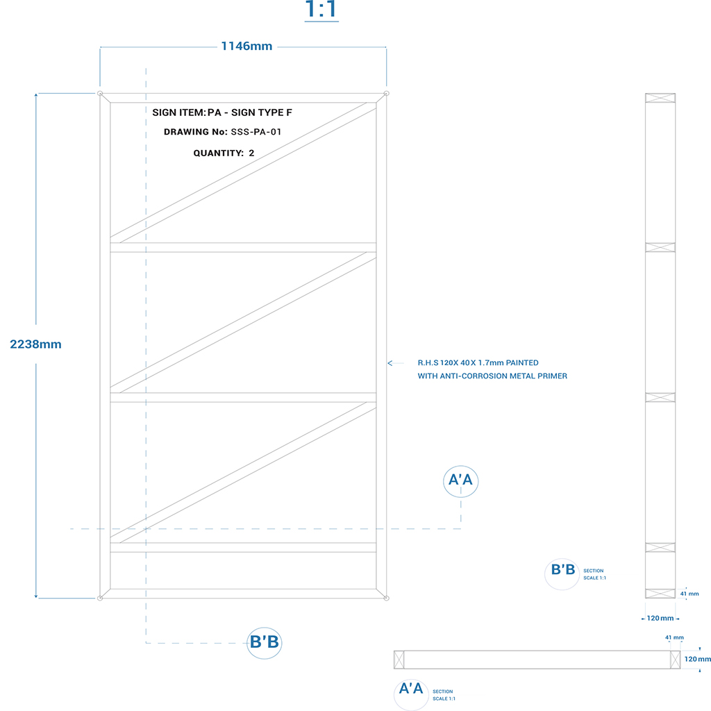
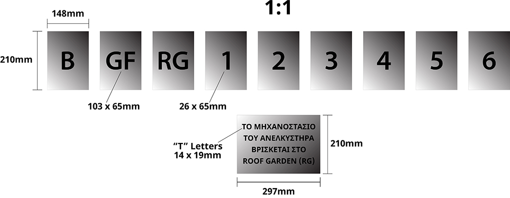
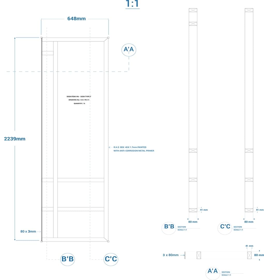
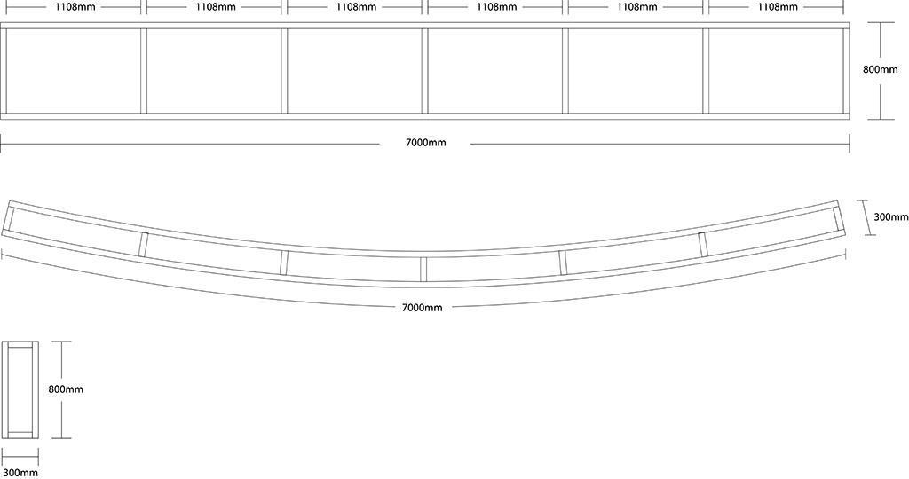
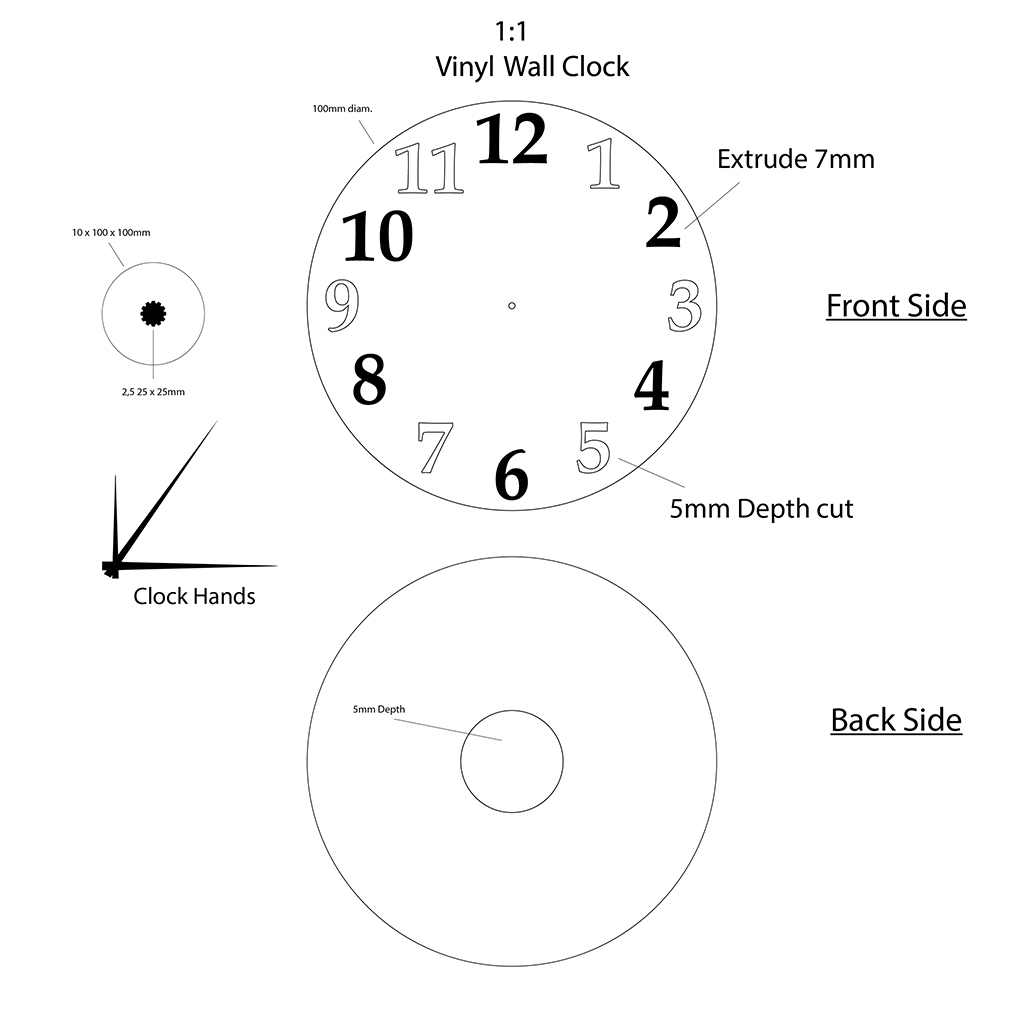
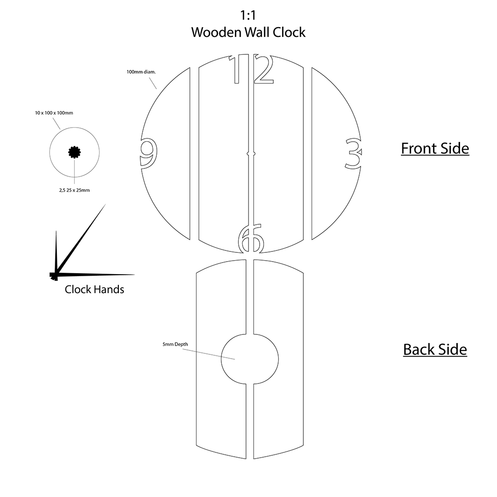
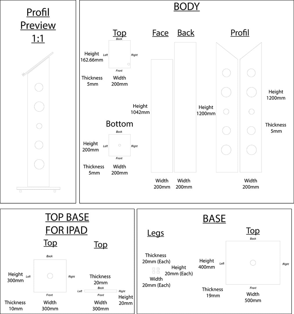
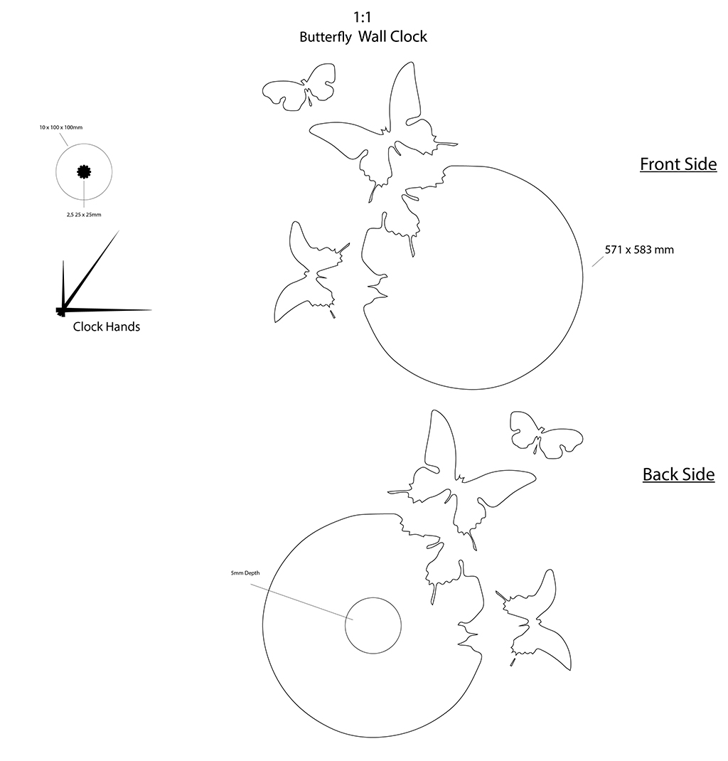
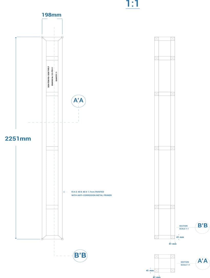
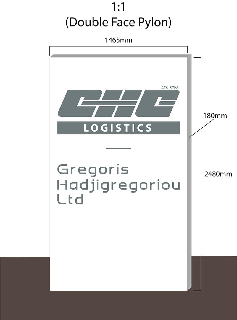
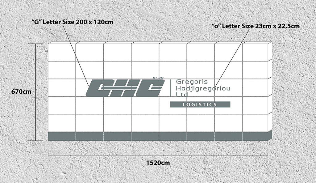
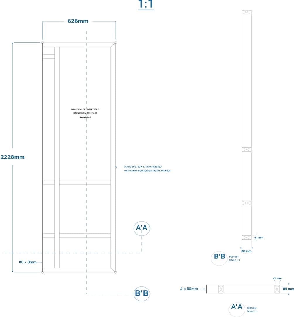
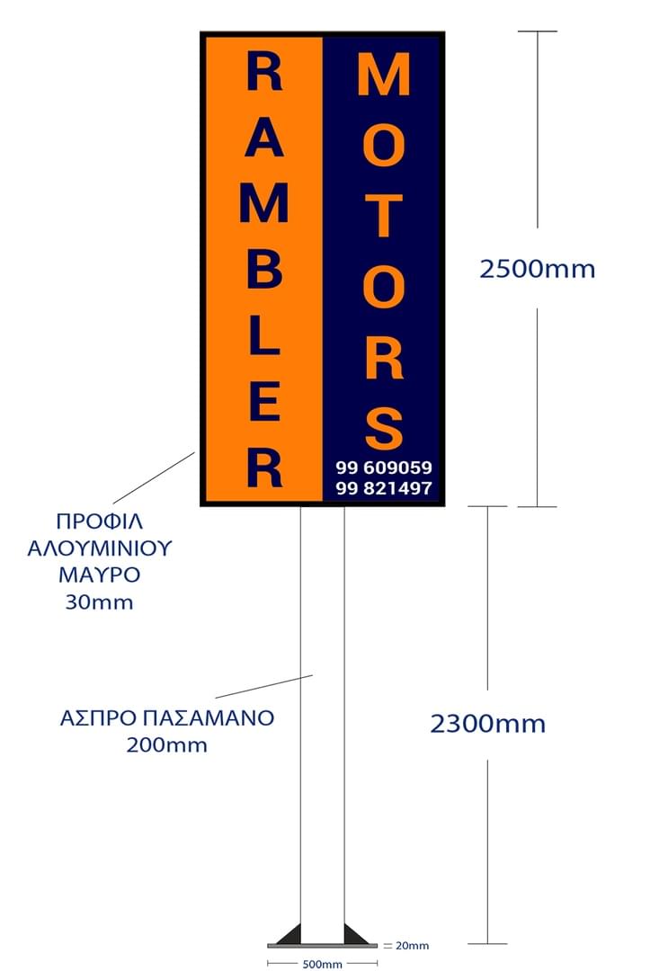
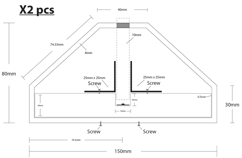
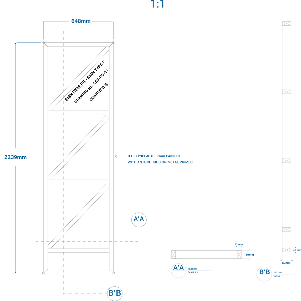
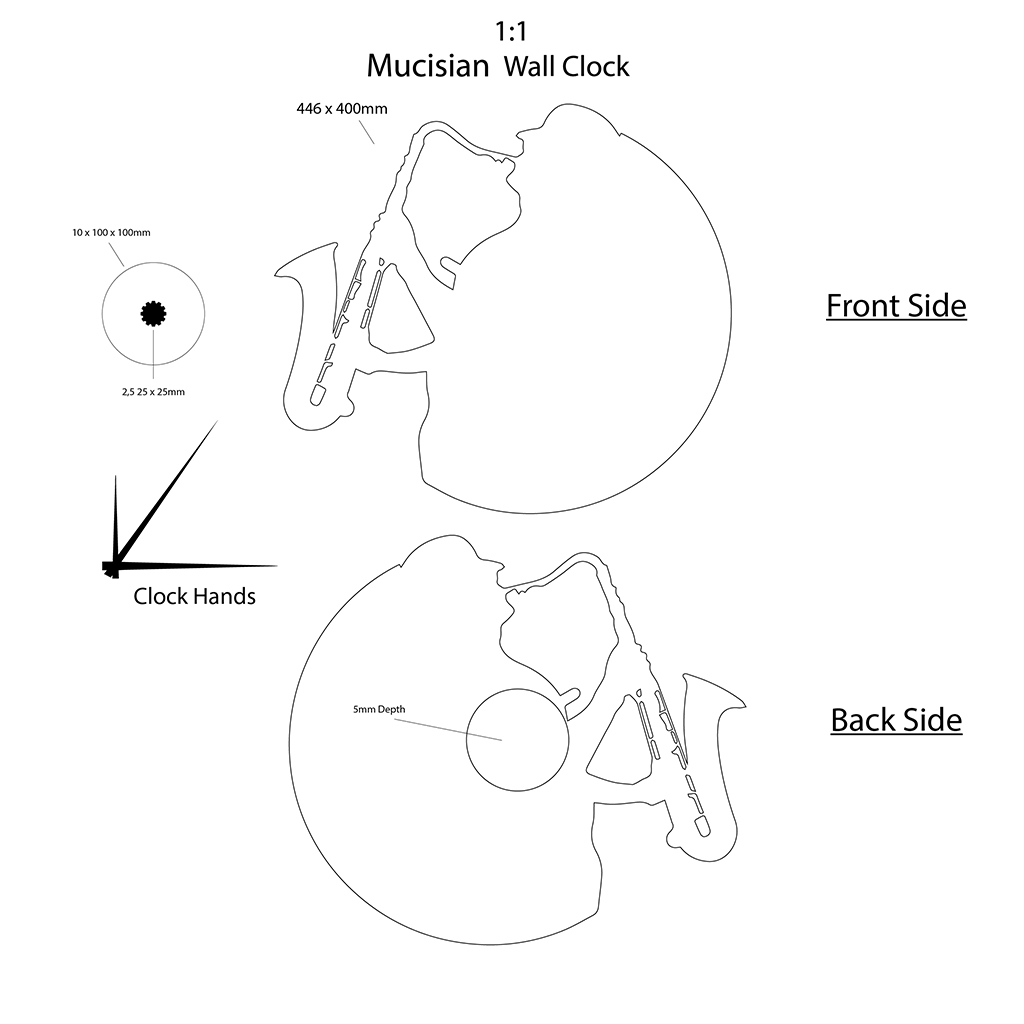
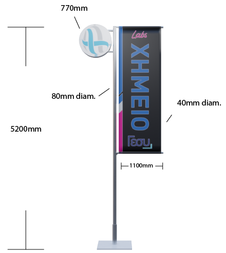
The term ‘technical drawing’ has a very broad meaning, referring to any drawing that conveys the way that something functions or how it is constructed. Technical drawings are intended to convey one specific meaning, as opposed to artistic drawings which are expressive and may be interpreted in a number of ways.
Most drawings prepared during the design and construction of buildings might be considered to be technical drawings.
Technical drawings will generally become more complete, more specific and will increase in detail as a project progresses. They may include:
•Sketches
•Design intent drawings
•Detail drawings
•Working drawings
•General arrangement drawings
•Assembly drawings
•Component drawings
•Shop drawings
•Installation drawings
•As-built drawings and record drawings
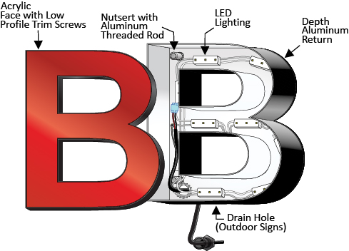
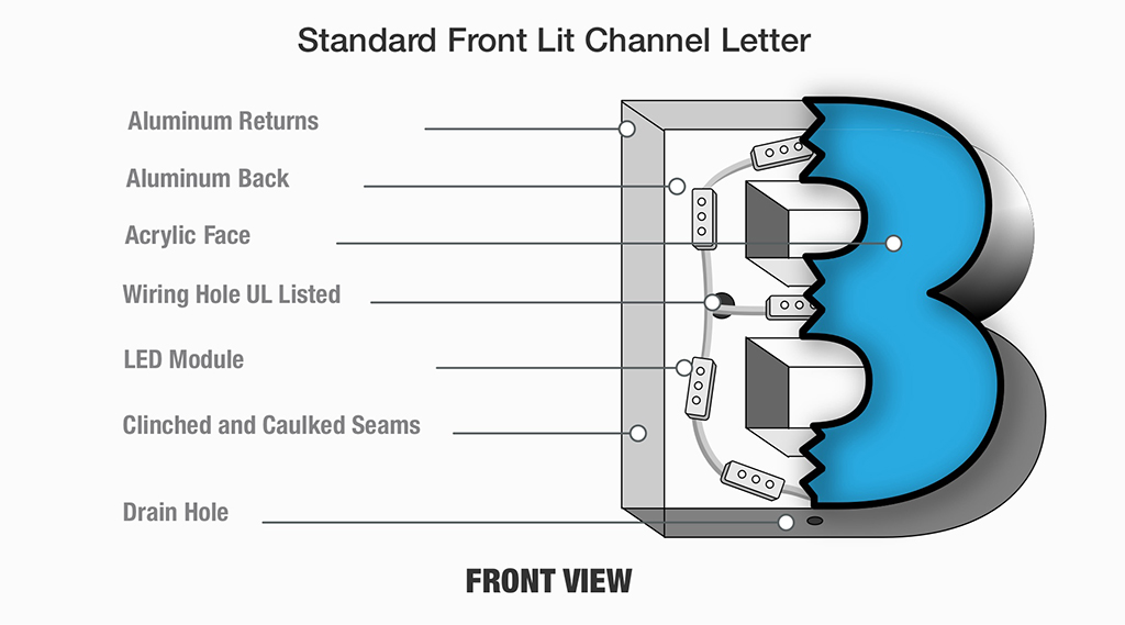
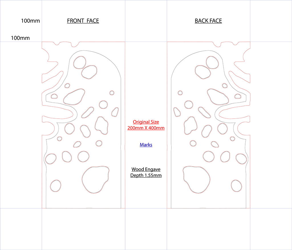
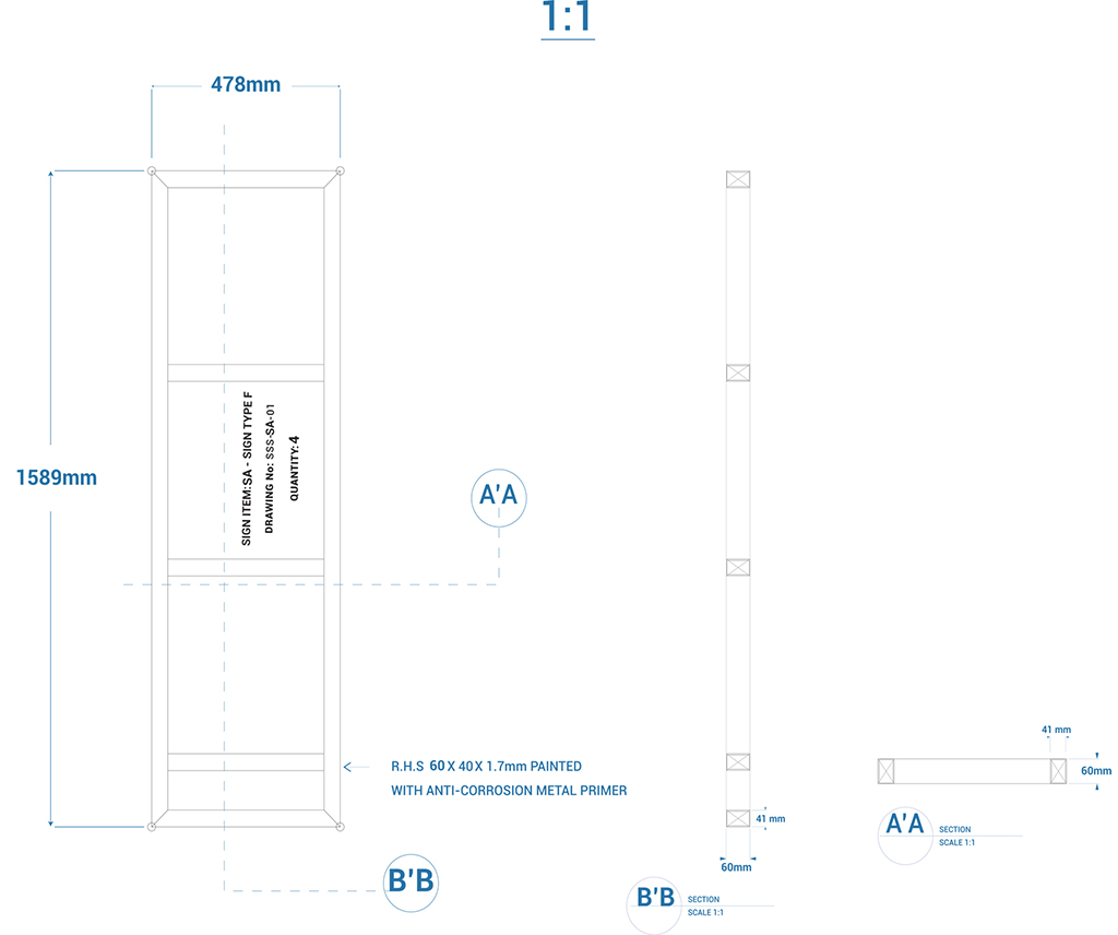
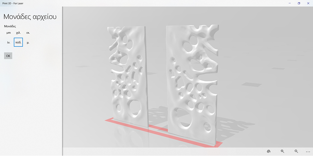
Technical drawings may comprise two-dimensional (orthogonal) plans, sections and elevations, or may include three-dimensional or exploded projections. They may be drawn to scale by hand, or prepared using Computer Aided Design (CAD) software. However, increasingly, building information modelling (BIM) software is being used to create three-dimensional representations of buildings and their components. BIM models may be described as 'design intent models' during the early stages of development but then may evolve into 'virtual construction models' (VCM) and finally 'as-constructed models'.
